3. Transformation Calculator
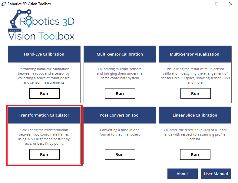
3.1. What is Transformation Calculator?
Industrial robots work in different coordinate frames, or user defined frames (UF). For example, users can jog the robot in the tool frame under a specific part frame while take 3D measurement in the sensor frame when doing part inspection or guidance. User will need to convert the position of the critical features from the sensor frame all the way to the part frame, or even to the part CAD frame. The Transformation Calculator provides many alignment methods that cater to users’ needs.
3.2. Calculation Procedure
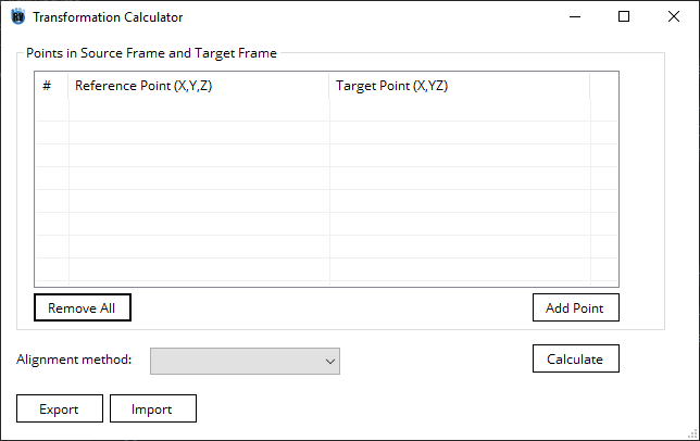
Add a minimum of 3 Alignment Points (Add point). Each alignment point represents a pair of Source Points and the Target Points.
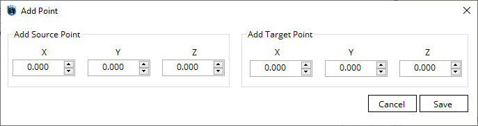
Each point contains axis \(x\), \(y\), and \(z\), and each axis has the Source Point and the Target Point value.
In most cases, Source Point represents the point in the CAD coordinate frame, while Target Point represents the point in the measurement coordinate frame.
Therefore, oftentimes Source Point is a constant value while Target Point is an expression that contains the measurement from a sensor.
Select the
Alignment methodto be used.Configure the alignment point/Axis.
Note
Refer to Alignment Methods for more info.
Click Calculate button to calculate the UF.
3.3. Alignment Methods
3.3.1. Overview
There are three choices for alignment methods:
3.3.2. Best-Fit by Point
Best-Fit by Point is a purely analytical method in linear algebra. It tries to compute a transformation matrix \(T\) such that
where \(point_{source}\) and \(point_{target}\) are the same point expressed in the CAD coordinate frame and the measurement coordinate frame, respectively.
Note
Input
Minimum 3 Alignment Points
Maximum error threshold
Output
The transformation from the source coordinate frame (nominal or CAD) to the target coordinate frame (measurement)
Error
Advantages
The most robust and reliable method
A result is guaranteed
Disadvantages
The xyz values of all points must be present and accurate
3.3.3. Best-Fit by Axis
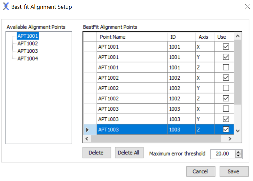
Best-Fit by axis is a numerical algorithm that is iterated until it converges. It is often used when CAD puts a higher tolerance on certain axis, so the user wants to exclude them and select only the most critical features to compute the alignment.
It tries to compute a transformation matrix \(T\) such that
where \(point_{source}\) and \(point_{target}\) are the same point expressed in the CAD coordinate frame and the measurement coordinate frame, respectively.
Important
Unlike Best-Fit by Point and 3-2-1 alignment, the user needs to select critical axis by checking the Use check box.
Note
Input
At least 4 Alignment Points and at least 6 critical axes
Output
The transformation from the source coordinate frame (nominal or CAD) to the target coordinate frame (measurement)
Error
Advantages
Can exclude certain inaccurate axes from the model
Disadvantages
It may fail due to a singular matrix
It may fail to converge, depending on the combination of the critical axes
It may fall into a local minimum solution
3.3.4. 3-2-1 Alignment
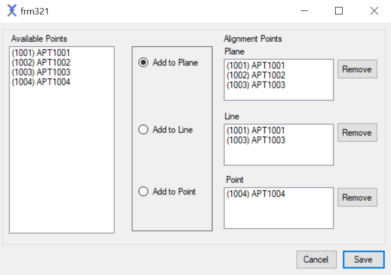
3-2-1 alignment is a purely analytical method that aligns 2 coordinate frames by consecutive 3D transformations. .. It tries to compute a transformation matrix \(T\) such that
Note
Input
3 Alignment Points to define a plane, 2 Alignment Points to define a line, and 1 Alignment Point to define a point.
Output
The transformation from the source coordinate frame (nominal or CAD) to the target coordinate frame (measurement)
Advantages
A traditional alignment method that is familiar to most engineers
More flexibility. The 3 points to define the plane and the 2 points to define the line don’t need to be the exact same points in the CAD and the measurement frame.
Disadvantages
It may fail due to singular matrix
Requires at least 6 points
Warning
Because 3-2-1 alignment is a purely analytical method, there isn’t a maximum error threshold to reject the wrong result.
The users are encouraged to select some features on the CAD coordinate frame, apply the transformation, and check if they fall on the same feature in the measurement frame.
Tip
The 3 points that define the plane in the CAD coordinate and the measurement coordinate don’t have to match one another, but they must follow the same rotational motion (clockwise/counter-clockwise) with respect to the plane normal axis.
The 2 points that define the line in the CAD coordinate and the measurement coordinate don’t have to match one another, but the order matters because they define the positive direction of the axis.
Some Examples are shown at the end of this page.
3.4. Examples
We provide some examples from our industrial partners use it. Users can refer to the examples here when they are setting up a UF alignment model in their own project.
3.4.1. 3-2-1 Alignment
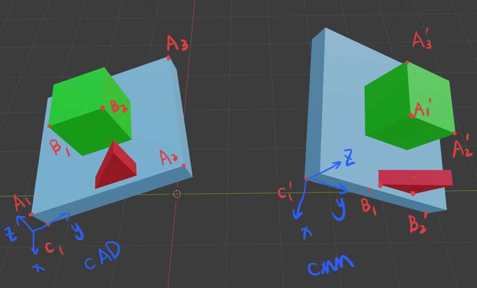
In this example, we have a rigid part that is composed of 3 blocks. The alignment point data are listed in the table below:
Point |
Feature |
CAD x |
CAD y |
CAD z |
CMM x |
CMM y |
CMM z |
|---|---|---|---|---|---|---|---|
\(A_1\) |
Plane |
-0.9059 |
1.8839 |
1.4628 |
-0.6909 |
-3.5788 |
2.8062 |
\(A_2\) |
Plane |
-0.3528 |
-0.4718 |
1.9731 |
-0.1136 |
-4.3455 |
2.4007 |
\(A_3\) |
Plane |
2.0527 |
0.0345 |
1.7030 |
0.7861 |
-3.6854 |
2.9138 |
\(B_1\) |
Line |
0.1065 |
1.4756 |
2.3687 |
-0.6375 |
-3.3163 |
1.8573 |
\(B_2\) |
Line |
0.3007 |
0.6483 |
2.5479 |
-0.6726 |
-3.9218 |
1.5370 |
\(C_1\) |
Point |
-0.9285 |
1.8018 |
1.1081 |
-0.6152 |
-2.2206 |
2.0165 |
Tip
As you may notice, \(A_1\), \(A_2\), and \(A_3\) in the CAD coordinate don’t have to match \(A_1'\), \(A_2'\), and \(A_3'\) in the CMM coordinate. It doesn’t affect the final result because the 3 points define the normal vector to the same plane.
Similarly, \(B_1\) and \(B_2\) in the CAD coordinate don’t have to match \(B_1'\) and \(B_2'\) in the CMM coordinate, but it doesn’t affect the final result because they represent to the same directional vector.
\(C_1\) and \(C_1'\) must be the same point expressed in 2 different coordinate frames.
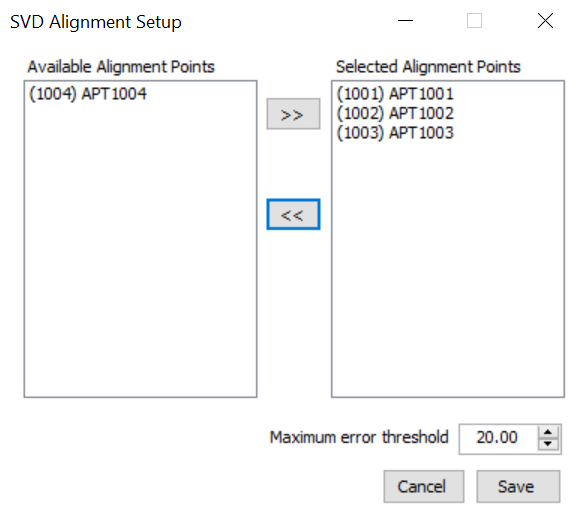
The figure below shows the 3-2-1 alignment setup window and the UF Transformation Calculator window.
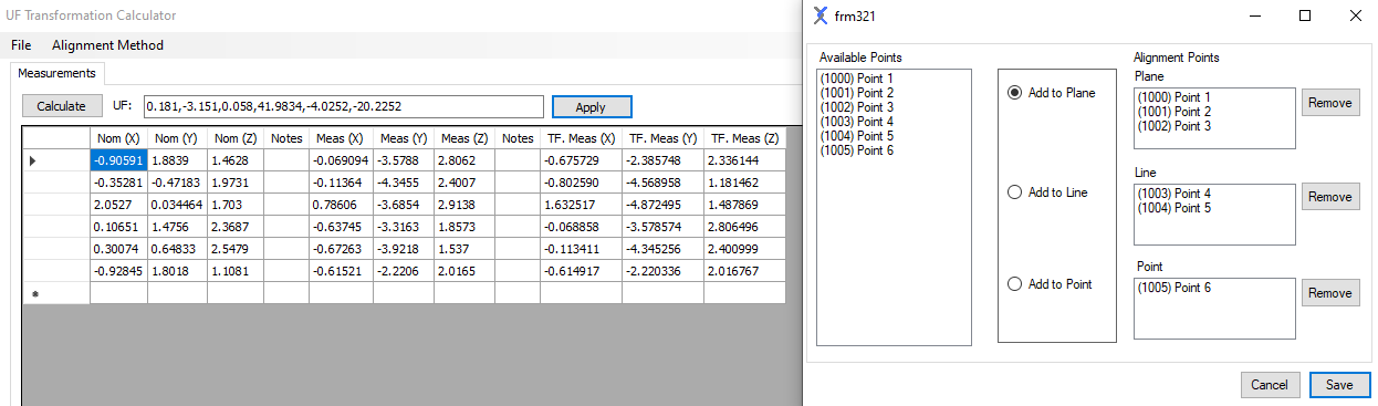
The final result of transformation \(T\) in x-y-z Euler angle (deg) format is
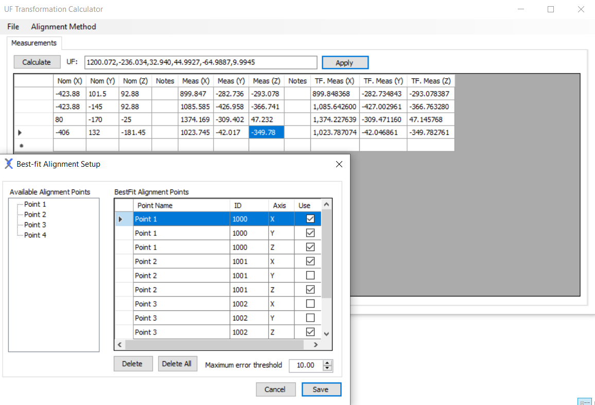
3.4.2. Best-fit Alignment
In this example, we selected 4 points, i.e. 12 axes in total. 6 of them are critical.
The alignment point data are listed in the table below:
Point |
Critical |
Nominal |
Measured |
|---|---|---|---|
1_x |
1 |
-423.880 |
899.847 |
1_y |
1 |
101.500 |
-282.736 |
1_z |
1 |
92.880 |
-293.078 |
2_x |
1 |
-423.880 |
1085.585 |
2_y |
0 |
-145.000 |
-426.958 |
2_z |
1 |
92.880 |
-366.741 |
3_x |
0 |
80.000 |
1374.169 |
3_y |
0 |
-170.000 |
-309.402 |
3_z |
1 |
-25.000 |
47.232 |
4_x |
0 |
-406.000 |
1023.745 |
4_y |
0 |
132.000 |
-42.017 |
4_z |
1 |
-181.450 |
-349.738 |
The final result of transformation \(T\) in x-y-z Euler angle (deg) format is