4. Pose Conversion Tool
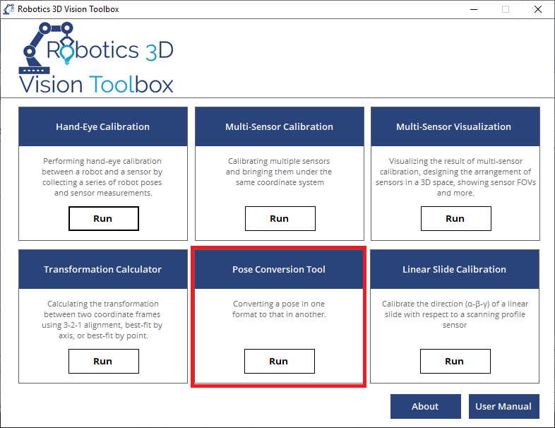
4.1. What is Pose Conversion Tool?
The Pose Conversion Tool is able to perform 3D pose conversion in different formats, a variety of 3D pose algebra such as multiplication/difference/inverse, and pose transformation. It can be used in a robotics and sensor system for quick verification and calculation; it can also be used as a mathematical tool especially in the field of robotics and computer vision. The pose conversion tool is composed of three different tabs and thus three different functionalities. They are explained in the following three sections
4.2. Frame Format Conversion
The frame format conversion tool can convert a pose in any robot format into all other formats. The supported formats includes Euler ZYX, Euler XYZ, axis-angle, quaternion and transformation matrix.
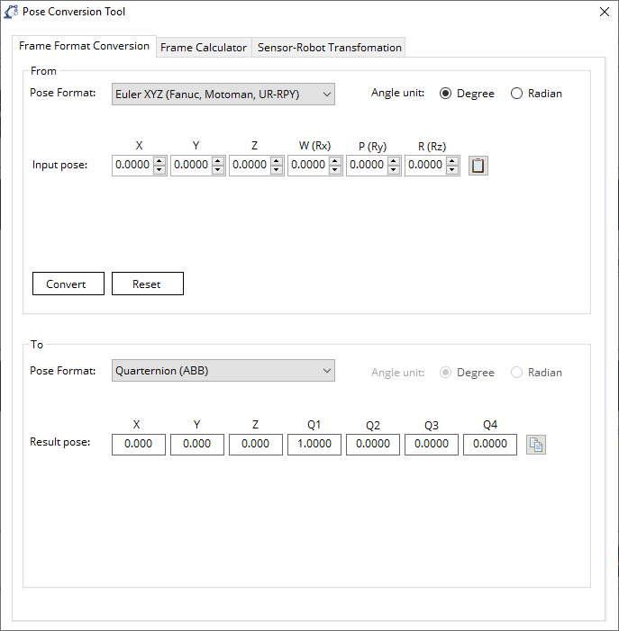
4.2.1. Inputting the source pose
In the
Frombox, first select the format of the source pose from thePose Formatdropdown menu. If the selected format is Euler ZYX, Euler XYZ, or axis-angle, please also choose the unit of the angle in the rotation part of the pose inAngle unitbetween degree and radian.If the selected format is Euler ZYX, Euler XYZ, or axis-angle, please input the six vaules of the pose in
Input pose. If the selected format is quaternion, please input the seven values of the pose inInput pose. If the selected format is transformation matrix, please input the first three rows of the matrix inInput matrix. The last row of the matrix will always be [0 0 0 1]. Instead of typing the values one by one, the user can also copy the pose or matrix from a spreadsheet and click Paste to input the pose or matrix.
4.2.2. Getting the converted pose
After inputting the source pose properly, click Convert to see the converted results in the
Tobox.To display the results in the desired angle unit, choose between degree and radian in
Angle unit. Again, the unit of angle only affects Euler ZYX, Euler XYZ, and axis-angle.The user can click button Copy after each pose or matrix to copy the corresponding result to clipboard.
4.3. Frame Calculator
The frame calculator tool can perform pose algebra such as multiplying two poses, transforming a point with a pose, calculating the difference of two poses, inverting a pose.
Note
All the poses used in this tool will be in the Euler ZYX format.
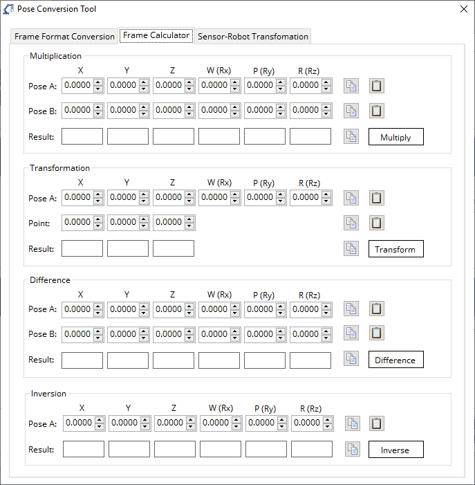
Multiplication: The
Multiplicationfunction calculates the product of the two input poses using formula Result Pose = Pose A * Pose B.Transformation: The
Transformationfunction calculates XYZ coordinates of a point under frame A after being transformed into frame B. The pose to be input is the transformation from the target frame (frame B) to the original frame (frame A). The point to be input is the XYZ coordinate of the point in the original frame (frame A). The calculation is perfomed using formula Point in B = Frame B to A * Point in A.Difference: The
Differencefunction calculates the difference of the two input poses using formula Difference = inv(Pose A) * Pose B.Inversion: The
Inversionfunction calculates the inverse of the input pose.
4.4. Sensor-Robot Transformation
The Sensor-Robot Transformation is used to transform the XYZ coordinates of a point in the sensor frame back to the robot frame or part frame, in the circumstance where a sensor is mounted onto the flange of a robot and measures the XYZ coordinates of a point on a part.
Note
All the poses used in this tool will be in the Euler ZYX format.
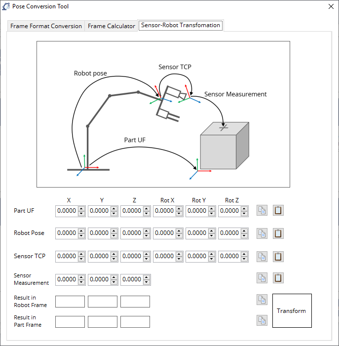
Part UF: The transformation from the robot base frame to the part frame. This frame is optional unless the Result in Part Frame is to be calculated.
Robot Pose: The pose of the robot, which can be read from the teach pendant of a robot. If the robot pose is in a different format, please use our Frame Format Conversion tool to convert it into Euler ZYX format.
Sensor TCP: The transformation from the robot flange to the sensor frame. It can be calibration using our TCP/UF Calibration toolbox.
Sensor Measurement: The measured XYZ coordinate of the point on a part.
Result in Robot Frame: The transformed result of the XYZ coordinate of the point expressed in the robot base frame.
Result in Part Frame: The transformed result of the XYZ coordinate of the point expressed in the robot base frame. This result is valid only when the Part UF is input correctly.