5. Multi-Sensor Visualization Tool
Important
Although the Multi-Sensor Visualization tool is a web-based application, most processing and rendering are done offline. The sensor arrangement, the sensor model selected, and the .stl file imported stay locally in the user’s PC. (i.e. Your models are NOT uploaded to our server.)
The web app communicates with the server only when the user adds a sensor to the scene. (It needs to get the sensor size, FOV, etc. from the database)
5.1. What is the MultiSensor Visualization Tool?
The 3D visualization tool can show multiple profile/snapshot sensors under the same coordinate frame. Thanks to the sensor library, we are able to to display the sensors in their actual sizes with their actual FOV (Field Of View), making it possible to:
Select the sensor that suits the project needs
View the sensor resolution and FOV at different height
Position multiple sensors around the CAD of the part to help make designing more efficient
Visualize and verify the multi-sensor calibration result
Warning
We model the sensors and their FOVs using simple geometries. We also assume that the laser aperture is located at the center of the bottom of the sensor.
Therefore, please be advised that the 3D visualization tool serves as a reference for the design, and it doesn’t serve as a substitute for the official emulators provided by the manufacturers.
5.2. Basic Guide
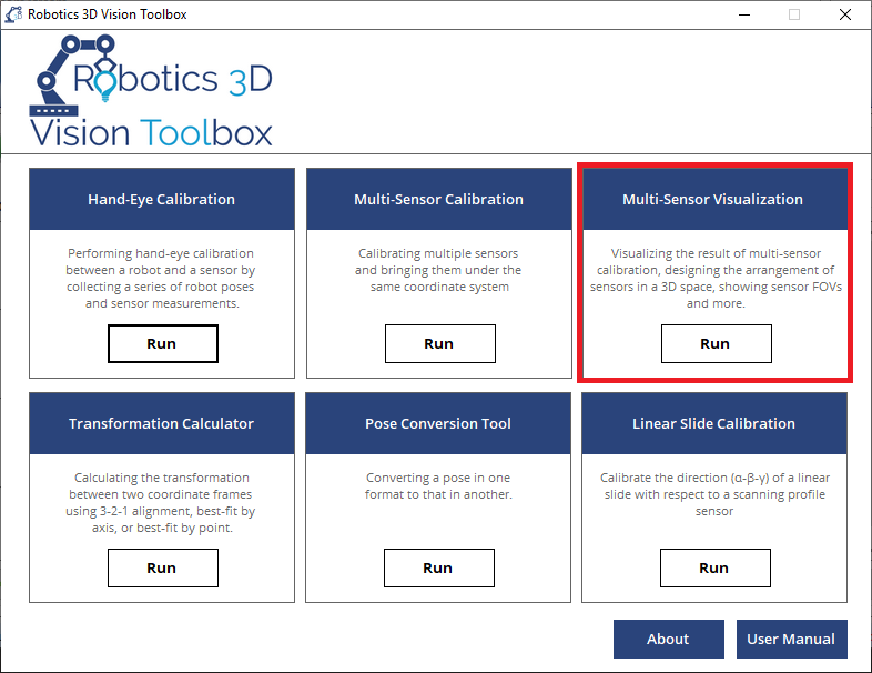
5.2.1. How to run the program?
The 3D visualization tool is a web-based app developed and supported by most modern web browsers (e.g., Chrome, Firefox, Microsoft Edge). Open the 3D visualization tool from the Robotics Vision Toolbox main panel.
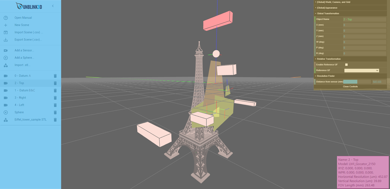
5.2.2. Workspace Overview
The Scene (Dark Grey) is where the sensors and other 3D objects are displayed. Use Left Click to select a sensor, Left Drag to orbit the camera, Middle Scroll to zoom, and Right Drag to pan the camera.
The Sidebar (blue) on the left allows users to add or remove a sensor/sphere/.stl model. It can also import the final result (.csv) from our Multi-Sensor Calibration Tool.
The Property Panel (yellow) on the top right allows users to change the position/orientation of the selected object, modify the appearance of the sensors and the scene.
The Info Window (red) at the bottom right displays information of the selected object.
Note
Gimbal Lock
The camera has a gimbal lock that stops the user from orienting the camera freely. However, the user can go to [Global] World, Camera, and Grid and check Invert Camera Gimbal Lock to flip the direction of Z axis. This would help create a better representation of the actual sensor configuration under some situations.
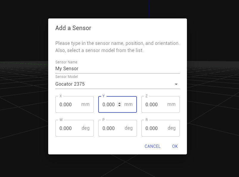
5.2.3. Adding a sensor
Click Add a sensor… on the sidebar.
Select the sensor model from the dropdown list. Type in the sensor name and XYZWPR.
Note
If you cannot find the sensor model, contact us and we will add it to the sensor library.
Click OK and the model of your choice will be added to the scene after loading.
Note
The web app talks to the server to retrieve sensor data. It may take several seconds.
5.2.4. Adding a sphere
Click Add a Sphere/Point… on the sidebar.
Type in the Name of the sphere.
Select a Reference Coordinate Frame. The sphere will be positioned with respect to the selected coordinate frame.
Type in the the X, Y, Z, diameter in mm. A sphere will be added to the scene.

5.2.5. Moving a sensor manually
Left Click the sensor in the Scene or on the sensor on the Sidebar. The color of the sensor changes, indicating that the sensor is selected.
Go to Transformation tab and change the XYZWPR of the selected sensor. There are 2 ways to move the selected sensor:
Type in the values in mm
Left click and drag the mouse vertically
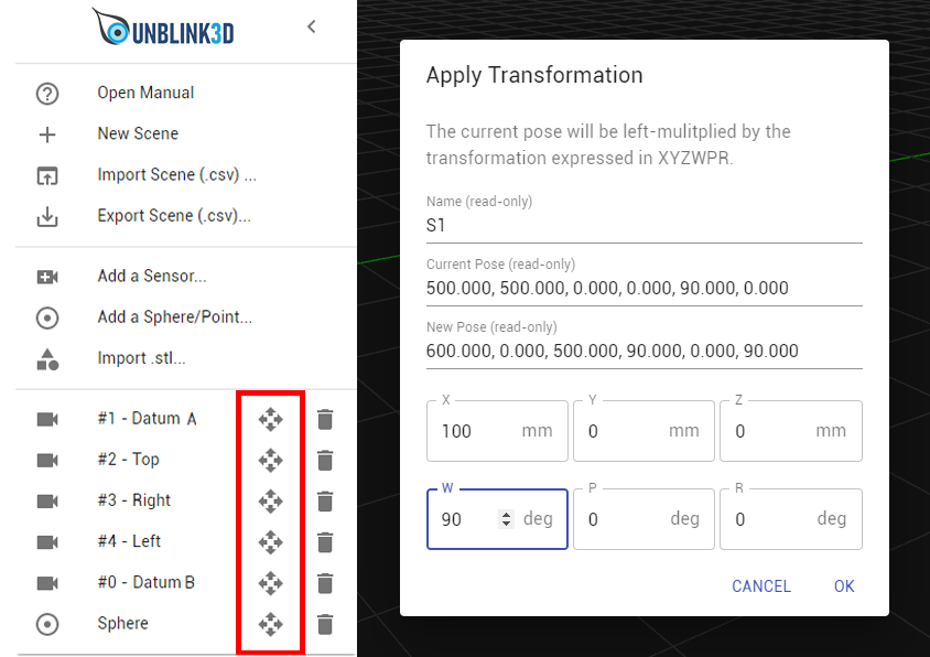
5.2.6. Apply a transformation to an object
Left Click the Transformation icon on the Sidebar.
Type in the transformation in the format of X, Y, Z, W, P, R. The new pose will be displayed for preview.
Click OK to apply the transformation.
5.2.7. Removing a sensor
Click the garbage bin icon next to the select in the Sidebar.
5.2.8. Importing a .csv file
The multi-sensor calibration tool allows exporting the final result as a .csv file. Below is an example of the .csv file exported:
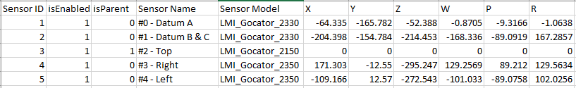
SensorID: the ID of each sensor
Sensor Name: the name to be displayed in the Info Window.
XYZWPR: the position and orientation of the sensors. Sensor positions are in mm, and sensor orientations are in degrees. The orientation follows x-y-z Euler angle format.
Warning
The 3D visualization tool recognizes a valid .csv by looking at the header, so don’t modify the header of the columns in the .csv file.
5.2.9. Importing a .stl file
When designing the sensor configuration, the user might need to import the CAD of the part to be scanned. Currently .stl format is supported.
Click Import .stl… on the Sidebar.
Since .stl files are unitless, type in the unit in the popup window. For example: mm, cm, in, etc.
The CAD file is loaded to the scene. It may take several seconds if the file is large.

5.2.10. Finding out the resolution at a given height
In general, the closer the object to the sensor, the higher the resolution. The tool provides a resolution finder feature based on the assumption that the relationship between sensor resolution and the distance to the sensor is linear.
Note
Some vendors only provide resolution in one direction; in that case, NaN is displayed.
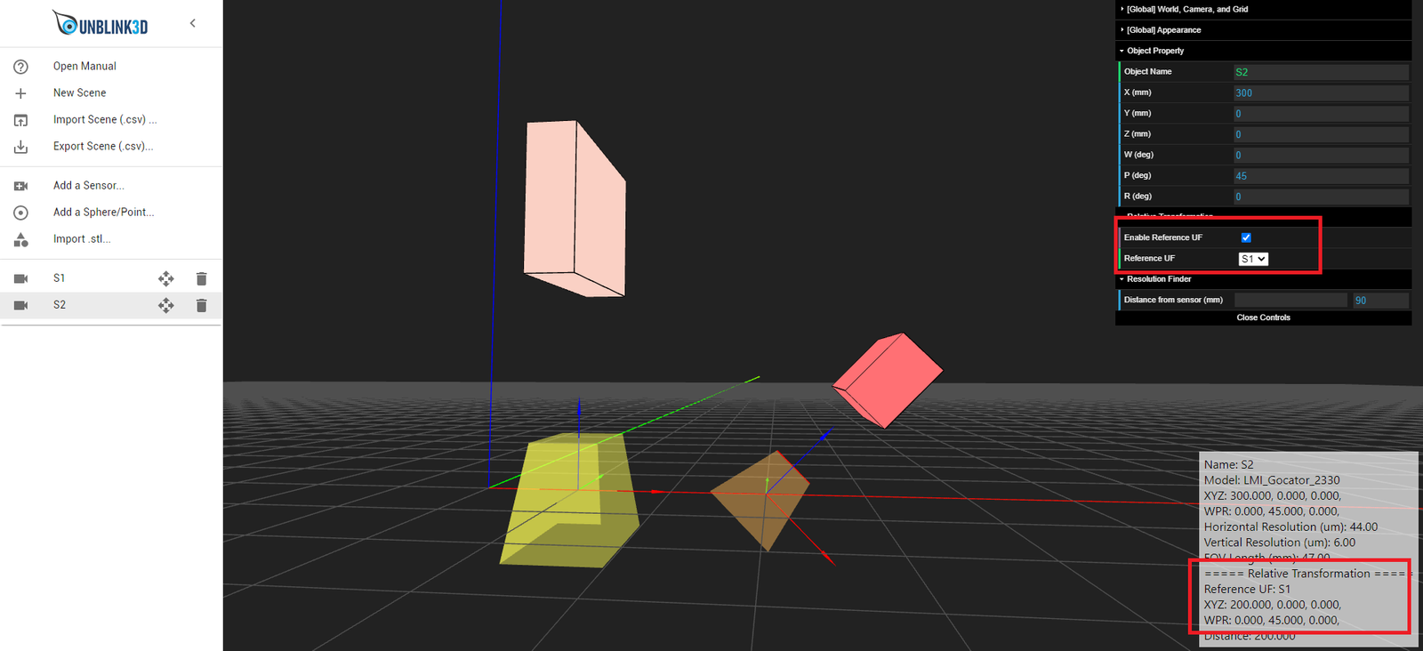
5.2.11. Finding out the relative transformation between sensors
The 3D visualization tool can show not only the sensor XYZWPR in the global coordinate frame, but also in the UF of other sensors.
By selecting Enable Reference UF and picking up a reference UF, the Info Window displays the XYZWPR of the selected object with respect to the Reference UF.