Case Studies
Case Study – Inline Bead Inspection Engine Cover

Aug
The Application
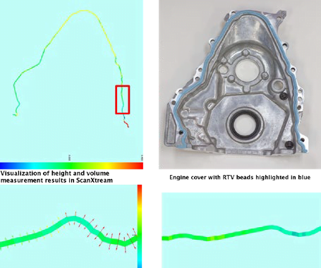
A global Tier-1 automotive supplier requires an automatic robotic system to inspect an engine cover RTV (room-temperature vulcanizing) bead for defects. Vision Adhesive Beads Inspection using Unblink3D software can handle it utilize 3D vision machine to compare and detect differences.
The Challenge
The RTV adhesive bead creates a seal between the engine cover to prevent leaks during operation. The correct and consistent volume of RTV bead applied is critical to ensure a correct seal to prevent leaks that can lead to potential recalls.
The customer’s specifications included checking for the width, height, and continuity of the bead. Because of the height requirement and the color of the bead, a 2D or manual inspection process was not possible because it would not provide the accuracy needed to inspect the consistent amount of RTV bead application.
The choice of a 3D camera system was important to prevent noise caused by the shiny machined surface of the part. Furthermore, the system needed to be fast enough to process the data within a few seconds and return the pass/fail information to the line PLC.
The Solution – Vision Adhesive Beads Inspection
Based on the customer’s requirements, a 3D scanning system was suggested to collect the height and width information. The 3D scanner would be mounted to an industrial robot that would move the scanner along the bead. Other configurations were also feasible, for example, the part held by the robot to be scanned by a fixed camera or having the camera mounted on a linear slide.
The system would communicate to the Unblink3D automation engine and communication software comXtream. The scanned data would be sent to ScanXtream, the 3D point cloud processing and viewing software, to identify the RTV bead dimensional properties to provide further analysis and inspection.
Image Alignment & Filtering
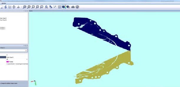
One or more-point clouds were sent into ScanXtream as shown in Figure 2a. With the CAD model also loaded into the software, the point cloud is automatically aligned to the CAD. If the CAD model was not available, the user could setup alignment based on the best fit of multiple features. Then these point clouds would be filtered to get the point clouds of the bead (Figure 2b).
Bead Inspection Setup
The following parameters for the bead inspection tool are available in ScanXtream:
Inspection Resolution – The distance between each
checking point needs to be smaller than the discontinuity tolerance. In this application 1.5 mm is used as the inspection resolution.

Max/Min Width – For each checkpoint, the width of the bead is measured. The part inspection will fail if the width at any checkpoint is out of tolerance. In this application, the max width is 5.5 mm and min width is 3.5 mm.
Max/Min Height (same as above) – In this application, the max height is 2.6 mm, and the min height is 2.0 mm.
Max/Min Deviation (optional) – To check the deviation of the bead from its nominal path, a list of points describing the nominal path needs to be provided.
The Results
In automatic mode, ScanXtream will send the inspection result (pass/fail) with coordinates of the failing checking points to comXtream for reporting purposes. However, within ScanXtream, the user can visualize the current or previous inspection results.